


")
- Price is excluding VAT
- Intelligent, compact, stackable microprocessor for smarter automation and process control
- Fully isolated standard analogue outputs 4-20mA and 0-10V
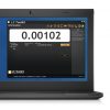
- Full digital setup & easy programming via handheld unit or USB connection to a PC using intuitive toolkit software.
- Increase reliability with 2 single pole relays & digital inputs
- 10 point linearization, providing superior accuracy
- 6 wire load cell connection to compensate for barrier and cable losses
- Lockable features prevents loss of device settings through user misuse
- Configuration can be saved and restored for security of setup
- Requires connection and configuration via PGM1 programming cable or LP2 handheld
- Have an Amazon account? Buy this product on our UK Amazon shop
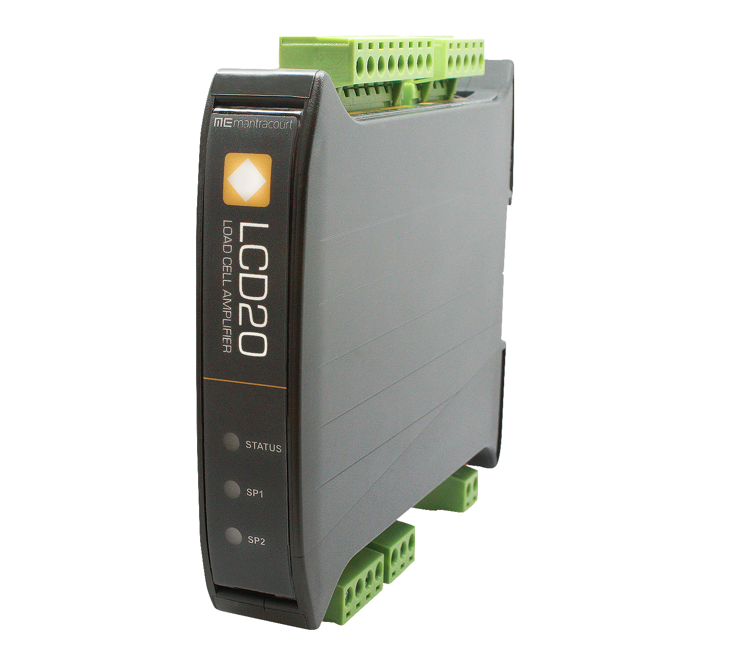
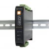
Load Cell DIN Rail Signal Amplifier (LCD20)
£253.00
Product Description
Our intelligent strain gauge bridge amplifier is a compact, stackable microprocessor based unit specifically designed to control and monitor process applications. Flexible connection to most load cells, pressure or strain gauges over a wide range of sensitivities. The unit provides isolated current 4-20mA and voltage 0-10V analogue outputs and two digital inputs. Two set point relays can be configured to set thresholds such as net, gross, peak and valley. Powered from a wide ranging DC supply, the DIN rail amplifier is supplied with 2 part screw connectors for ease of installation.
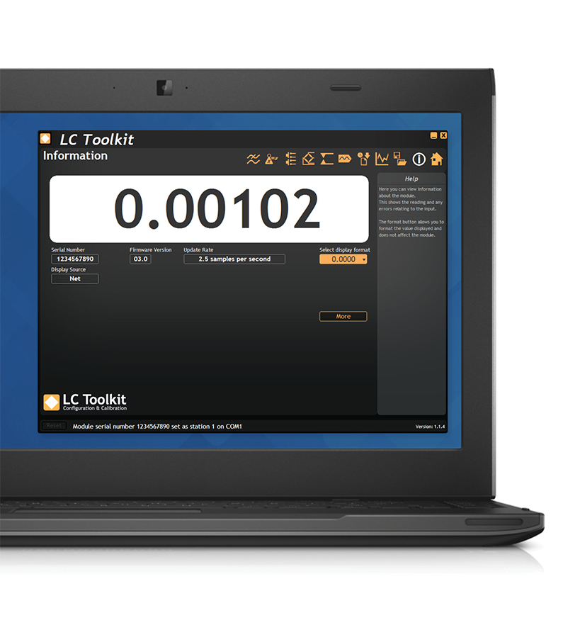
Suitable for strain gauges and other ratio-metric sensors and will support 6 wire input to compensate for barrier and cable losses. Factory calibrated to mV/V and supporting 10 point user calibration to desired engineering units. Configuration options via handheld programmer or PC Toolkit software.
The analogue outputs and relays interface to existing acquisition and control systems making this unit an ideal partner for any integrated instrumentation system.
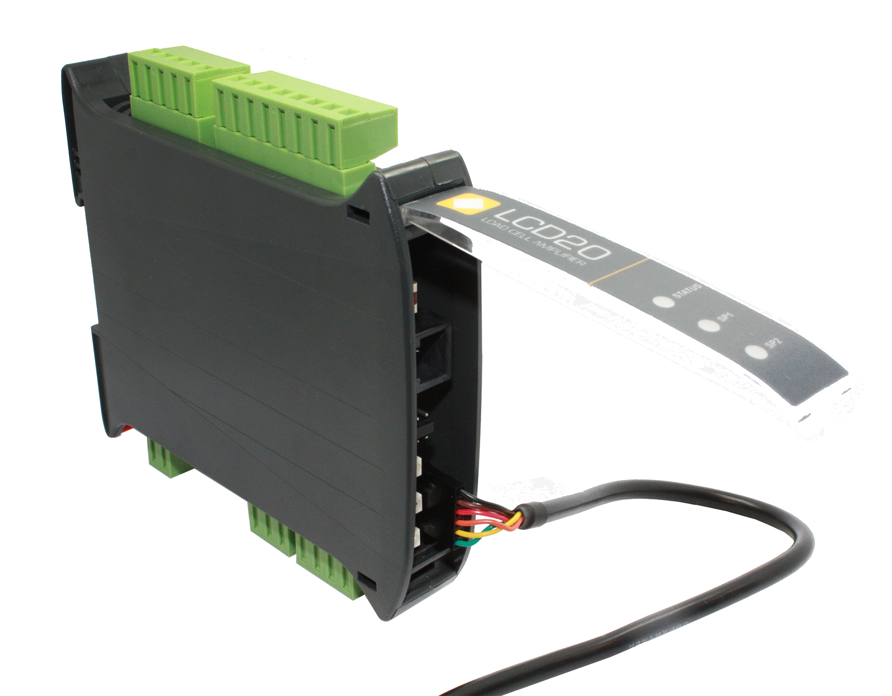
We offer two programming options for the LCD20. You will require either the PGM1 programming lead or the LP2 remote handheld to connect and configure to the LCD20.
All prices shown are per unit in pounds sterling and exclusive of VAT & delivery. VAT Reg No. 408973816. Subject to our Standard Terms and Conditions. Products Guaranteed for 3 years. In the interest of continued product development, Mantracourt Electronics Limited reserves the right to alter product specifications without prior notice.
Additional Information
| Weight | 0.5 kg |
|---|---|
| Dimensions | 29 × 24 × 16 cm |
| Actual Product Weight | 0.157 kg |
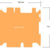
| Actual Product Dimension | 12 x 11.2 x 2.3 cm |
Dimensions
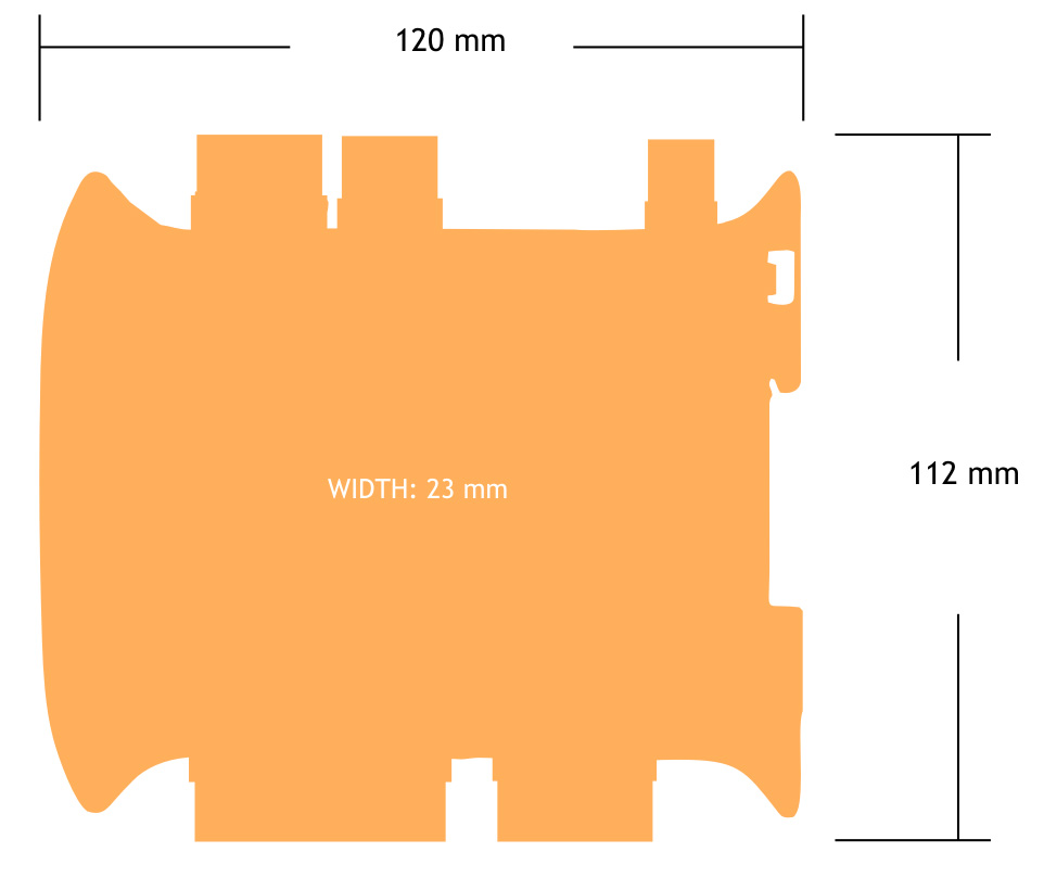
LCD20 Product Weight 0.157 kg
Installation & Connection
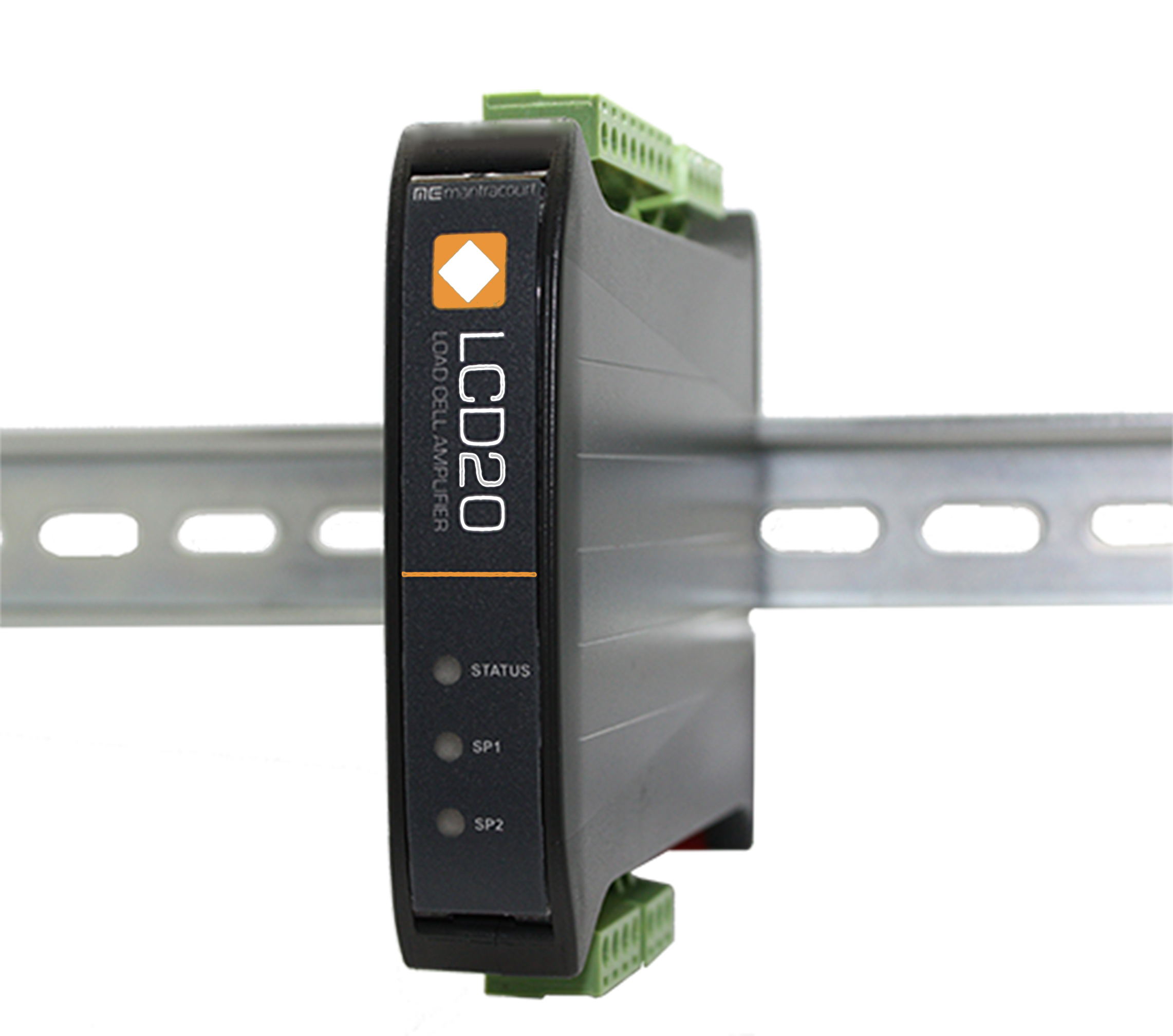
Mechanical
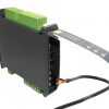
The LCD20 is designed to connect to a ‘Top Hat’ DIN rail.

Front Panel
Access to various connectors and buttons is gained by opening the front panel door. This is hinged at the opposite side to the LEDs.

CONNECTIONS

Load cell Connections
The LCD20 offers a direct connection to a range of low level (foil) strain gauge sensors.
Gain sensitivity is optimised for two ranges, 0.5 to 3.7mV/V and 3.7 to 7.8mV/V selected by the Sensitivity parameter in the menu.
A stable 5VDC excitation supply at 150mA is provided which is sufficient to power up to four 350 ohm load cells connected in parallel.
Ratiometric strain gauge measurements are taken which cancel out errors caused by changes or drift in Excitation voltage. The LCD20 facilitates 6 wire measurement which allows for voltage drops caused by long cable lengths between the LCD20 and the load cells, where barriers are used or if the load cells are powered from another source. Where possible, use 6-wire connections to the load cells.
For load cell connections we recommend the use of 3 pairs of twin twisted pair cable such as Alpha Wire 5123C SL005 available from Farnell 130-2249.
The pairs should be arranged as follows:
Excitation pins 1 & 6
Sense pins 2 & 5
Signal pins 3 & 4
Download

Manual Product Sheet
FAQs
Answer:
The LCI is powered from the connected instruments excitation supply.
The LCI is powered from the connected instruments excitation supply.
Answer:
Yes, the new version now supports 4-12V supply voltage which makes is more usable with modern instruments that supply 5V dc to the strain bridge.
Yes, the new version now supports 4-12V supply voltage which makes is more usable with modern instruments that supply 5V dc to the strain bridge.
Answer:
The LCI scans each load cell in turn measuring the mV of each load cell attached this allow for the following conditions to be tested for…
• One or more of the load cells are out of balance with the pre-set error band.
• Any load cell is operating outside its pre-set range
• The load cell excitation voltage drops
• Any of the load cells become open or short circuit
• Internal load cell fault causing bridge imbalance
Faults are flagged by the illumination of the red LED and the drop out of the relay contact.
Answer:
Between 1 and 4
Between 1 and 4
Answer:
There are no options for the LCI
There are no options for the LCI
Answer:
The following Mantracourt devices or families are compatible with the LCI
ADW15, LCA15, LCA20, LCD20, SMW and SGA
The following Mantracourt devices or families are compatible with the LCI
ADW15, LCA15, LCA20, LCD20, SMW and SGA
Answer:
The LCI is configured using the on board keypad and display. There is a simple single level menu system that is password protected that allow the 5 parameters to be entered.
The LCI is configured using the on board keypad and display. There is a simple single level menu system that is password protected that allow the 5 parameters to be entered.
Answer:
When the system is healthy and all load cells are operating within the parameters set the display will
Display “good”.
If there is an error the display will show the error codes. These codes relate to the load cell(s) causing the fault and an error number indicating what the fault is. Ie “2Er5” indicates load cell 2 has an excitation fault.
The display can also show the average mV value for the configured amount of load cells connected or show the individual mV for each load cell. Refer to manual for operation
Answer:
The LCI has a relay contact that is energised when the system is healthy. If a fault is detected the relay is de-energised and the red LED illuminated. It is this relay contact that can be used to indicate a fault to the up-stream system.
The LCI has a relay contact that is energised when the system is healthy. If a fault is detected the relay is de-energised and the red LED illuminated. It is this relay contact that can be used to indicate a fault to the up-stream system.
Answer:
The relay contact rating is 24V dc @ 500mA or 120V ac @ 500mA
The relay contact rating is 24V dc @ 500mA or 120V ac @ 500mA
Answer:
3 years
3 years
Answer:
IP65
IP65
Answer:
The cable diameter for the 6 glands is 4.5mm to 7mm
The cable diameter for the 6 glands is 4.5mm to 7mm
Answer:
Yes, the unit sums the connected load cells. The number of load cells is selectable on the the display.
Yes, the unit sums the connected load cells. The number of load cells is selectable on the the display.
Answer:
The max and min mV levels can be set in the range +/- 50 mV and are then applied to each load cell output.
The max and min mV levels can be set in the range +/- 50 mV and are then applied to each load cell output.
Answer:
Yes, the maximum allowed difference between load cell outputs can be set in the +/- 50 mV range.
Yes, the maximum allowed difference between load cell outputs can be set in the +/- 50 mV range.
Answer:
The LCI uses the excitation voltage that is provided to the load cells.
The LCI uses the excitation voltage that is provided to the load cells.
Answer:
There is an alarm LED on the LCI board that lights up when there is a fault. The display will show the load cell and error type. There is also a relay output to drive an alarm.
There is an alarm LED on the LCI board that lights up when there is a fault. The display will show the load cell and error type. There is also a relay output to drive an alarm.
1 review for Load Cell DIN Rail Signal Amplifier (LCD20)
Only logged in customers who have purchased this product may leave a review.
You may also like…
-
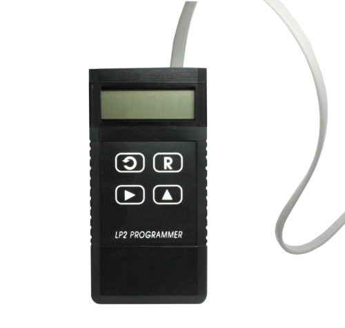
LP2 – Remote Handheld Programmer
£144.48 -
Mark Robinson –
We “stumbled” upon Mantracourt when we were searching for a supplier of load cell amplifiers for a precision testing machine. Our customer fast-tracked a control system upgrade that required 150 load cell amplifiers on a very short schedule. Mantracourt increased their production to meet our tight schedule and worked out the shipping details to our U.S. address. The quality was excellent and the pricing was extremely competitive. The LCD20 was very easy to install on DIN rails and calibration was simple and swift. We utilized their software to commission, calibrate and store the calibration profile of each LCD20 transmitter. The software installed without issues and was easy to use. We are delighted with the product, price and performance. Based on our experience, we highly recommend Mantracourt!”
Mark Robinson, Project Manager, Corsair Controls Inc.